


 Home
HomeStop Guessing: 7 Engineering Formulas to Match the Perfect UAV Battery
 2026-05-19
 0
0
Drone Battery Selection: Engineering Guide, Traps & 400Wh/kg
Quick Navigation (Table of Contents):
1. Voltage Platform Matching: Efficiency Optimization
2. Discharge Rates & Transient Voltage Sag
3. The Energy vs. Power Density Trade-off
4. Thermal Management Boundaries
5. Cycle Life Economics (TCO Model)
6. Dimension and Center of Gravity (CoG) Constraint
7.Selection Pitfall Checklist: Distilled from Engineering Failure Cases
8. Engineering Implementation Workflow
9.Capacity Sizing – From Formula to Practical Rule
10.Real-World Application – 30kg Mapping UAV Configuration
11. Why 400Wh/kg Semi-Solid-State Batteries Merit Serious Consideration

Target Audience: UAV Systems Engineers, Technical Procurement Specialists, and System Integrators.
Selecting a battery is not as simple as checking a capacity table. Once the motors are chosen, the propellers are fixed, and the flight controller is tuned, pairing them with an ill-fitted battery will effectively "weld shut" the performance ceiling of your entire system. Starting from engineering practice, this article provides quantifiable matching methods, mathematical explanations of common pitfalls, and insights into why 400Wh/kg semi-solid-state long endurance batteries are redefining the design boundaries for heavy-lift UAVs.
1. Voltage Platform Matching: Beyond "Adequacy" to the Efficiency Optimization Window
Basic Formulas:

Engineering Rules:
For a 12S platform (44.4V), it is recommended to control the voltage fluctuation range within ±10%.
Higher voltage means lower current (at the same power), reducing cable and connector losses.
However, excessive voltage leads to increased ESC switching losses, especially at high PWM frequencies.
Selection Advice: First, use the motor characteristic curve to find the voltage corresponding to the highest efficiency point, then determine the "S" count. The optimal voltage range for most medium-to-heavy lift UAVs (20-50kg) is between 44V and 52V, corresponding to 12S-14S drone battery.
Mindway Customization: UAV voltage optimization.We provide bespoke battery services from 4S to 14S versions to match different voltage platforms, avoiding the introduction of additional losses from being forced to use step-down modules due to voltage mismatch.
2. Discharge Rate Matching: The True Meaning of C-Rating and "Transient Voltage Sag"
A supplier’s claimed “15 C” usually refers to the maximum sustained rate under specific conditions (25 °C, 100 % SOC, cut‑off voltage 2.8 V/cell).
Key engineering metrics

Example calculation (12S battery, cell IR 3 mΩ)

Selection trap: Focusing only on the labelled C‑rate calculationhile ignoring actual internal resistance
UAV. Two batteries both labelled 15 C can have a difference of 1 mΩ in IR, leading to a 3.6 V difference in voltage sag at 300 A. Always ask the supplier for discharge curves at different C‑rates (including voltage vs. time at 25 %, 50 %, and 100 % SOC) — never rely solely on a C‑rate label.
Mindway Performance:Mindway’s 400 Wh/kg semi‑solid battery uses a low‑impedance interface design. The 12S 30 000 mAh version has a measured internal resistance ≤2 mΩ/cell at 3 C discharge, ensuring that voltage stays above 85 % of nominal during heavy‑lift take‑off.
3. Energy Density vs. Power Density Trade-off: High Energy Does Not Guarantee High Power
A 400 Wh/kg battery is very attractive, but high energy density often comes at the cost of power density (energy density vs power density) — unless a specific material system is used.
Physical constraints
Thicker electrode coating increases energy density but lengthens Li‑ion diffusion paths, reducing rate capability
High energy density usually employs high‑silicon anodes or high‑nickel cathodes, which require balancing cycle life and rate performance
Splitting strategy in engineering applications
Sustained tasks (cruise, hover): average power demand is low, energy density dominates
Transient tasks (take‑off, rapid acceleration, wind resistance): peak power demand is high, requiring sufficient power density
Practical approach:Draw the power spectrum of a typical mission profile(power vs. time). Calculate:

How to judge whether a battery matches

Mindway Innovation: The Mindway 400Wh/kg series utilizes semi-solid electrolytes + silicon-carbon composite anodes. At 400Wh/kg endurance gain, it can still achieve 3C continuous discharge and 5C peak discharge (some high-rate versions can reach 7C). For the vast majority of industrial UAVs (with peak power density requirements around 600-1000W/kg), this battery satisfies both energy and power demands.
4. Thermal Management Boundaries: The Quantified Impact of Temperature Rise
For every 10 °C increase in temperature, the cycle life of a lithium battery decreases by roughly 30‑50 % (Arrhenius model).

Practical engineering limits
During continuous discharge, internal cell temperature should be ≤60 °C
Surface temperature should be ≤50 °C (for contact safety and BMS protection)
Cell‑to‑cell temperature difference ≤5 °C, otherwise consistency degrades
How to select a battery with drone battery thermal management
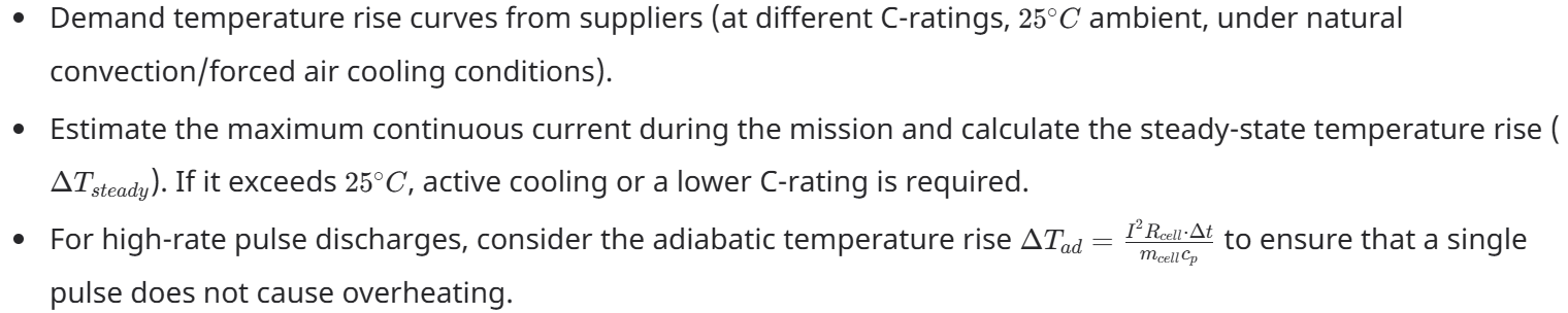
Mindway Reliability: Mindway's 400Wh/kg semi-solid-state battery exhibits superior thermal stability compared to liquid batteries (solid electrolytes reduce heat from side reactions); at the same current, the surface temperature rise is 8-12°C lower than traditional lithium-ion batteries. This is a critical reliability advantage for long-duration hovering or operations in high-temperature environments.
For an in‑depth engineering analysis on how heat drives battery swelling and thermal runaway—and why semi‑solid technology fundamentally solves these issues—please refer to our dedicated guide: [UAV Thermal Management: The Ultimate Guide to Battery Swelling & Cycle Life Degradation]
5. Cycle Life Economic Model: More Than Just a "Count"
A supplier's claimed "1000 cycles" is measured under specific lab conditions (usually 0.5C charge/discharge, 100% DOD, >
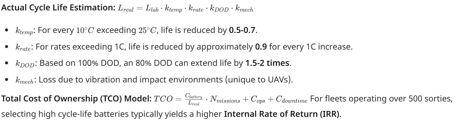
Mindway Efficiency: Mindway's 400Wh/kg semi-solid-state battery achieves a cycle life of >1000 cycles at 80% DOD, 1C charge/discharge, and
6. Dimension and Center of Gravity (CoG) Constraints
Many engineers only focus on weight, ignoring the impact of battery shape on the moment of inertia and CoG position.

Design Suggestions:
Prioritize flat, large-area battery layouts placed close to the CoG, and strive for symmetry with the airframe.
For multi-rotors, the battery CoG should deviate from the overall aircraft CoG by
< 5 % Battery dimensions should reserve a 5-10% cooling gap to avoid direct contact with the shell, which could cause heat soak.
Mindway Variety: The Mindway 400Wh/kg series provides a variety of packaging dimensions while also accepting custom shapes (such as curved fits for the fuselage or center-hole designs) to help integrators optimize the CoG and cooling airflow paths.
7. Selection Pitfall Checklist: Distilled from Engineering Failure Cases
| Pitfall / Symptom | Engineering Countermeasure |
|---|---|
| Only looking at capacity, ignoring internal resistance (Voltage sag at takeoff, flight controller alarm) | Measure or require DC Internal Resistance (DCIR) data at different SOC levels. |
| Nominal performance decay in high-temp environments (Endurance reduced by 40% in summer) | Request discharge capacity and C-rate data under 45℃ ambient conditions. |
| Incompatibility between battery and ESC (Regenerative energy) (ESC burnt due to overvoltage during braking) | Confirm ESC regenerative braking capability; the battery must support back-feed current |
| BMS communication protocol mismatch (Unable to retrieve SOC or health status) | Clearly specify BMS protocol (CAN, SMBus, UART) and request full protocol documentation. |
| Underestimating storage self-discharge (Unable to take off after battery idled for 3 months) | For non-daily missions, choose cells with self-discharge rates |
| Internal connection breaks caused by vibration (Sudden power loss during flight) | Check battery vibration testing standards (especially weld points and connector mounting methods). |
8. From Requirement to Specification: A 4‑Step Engineering Workflow for UAV Battery Selection
Step 1 – Gather system parameters

ESC: maximum continuous current, maximum instantaneous current, minimum operating voltage, PWM frequency
Whole drone: take‑off weight, mission profile (power vs. time), ambient temperature range, expected lifetime (cycles/year)
Step 2 – Iterative calculations
Determine the voltage platform (based on the point of highest efficiency)
Calculate the required capacity (based on average power × mission time ÷ voltage ÷ depth of discharge)
Calculate the required maximum current (based on peak power ÷ minimum allowable voltage)
Calculate the theoretical battery weight (energy requirement ÷ target energy density)
Verify thrust‑to‑weight ratio (motor thrust ÷ new total weight) ≥ 1.8 (safety factor)
Step 3 – Request and compare supplier data
Discharge curves (1 C, 3 C, 5 C, 10 C, at different temperatures)
Internal resistance (ACIR at 1 kHz, DCIR at 1 s/10 s)
Cycle life curves (at different DOD, temperature, and C‑rates)
Temperature rise curves (natural convection vs. forced air cooling)
Mechanical and environmental test reports (vibration, shock, IP rating, thermal shock)
Step 4 – Sample testing and validation
Mount a power analyser on the actual drone and measure the current profile of the mission
Compare against the new battery: voltage sag, temperature rise, and usable capacity – do they match the simulation?
Conduct at least 50 accelerated cycles to observe the capacity fade rate
9. Capacity Sizing – From Formula to Practical Rule
Capacity Calculation Formula :Capacity= (P_avg × T_mission) / (V_nominal × DOD)
Capacity: Required battery capacity (Ah)
P_avg = Average power demand over the mission profile (W), including hover, cruise, and reserved contingency power
T_mission = Target flight time (hours)
V_nominal = Nominal voltage of the battery pack (e.g., 44.4V for 12S)
DOD = Depth of Discharge (typically 80% to protect cycle life)
Engineering Design Margin Rule:
Multiply the calculated theoretical capacity by a safety factor of 1.15 to 1.25.
Why: This compensates for low-temperature conditions, battery aging, and unpredictable real-world factors like wind resistance and maneuvering that increase power consumption beyond ideal calculations.
10.Real-World Application – 30kg Mapping UAV Configuration
This case study demonstrates how to integrate the principles of voltage, C-rate, capacity, and thermal management into a complete selection process.
UAV Platform Parameters (Typical VTOL Fixed-Wing):
Take-off Weight: 30 kg
Mission Profile: Rolling take-off → Climb (3 min) → Cruise mapping (2 hrs) → Descent & landing
Power System: 12S platform, cruise power 800W, climb peak power 2500W
Target Endurance: 2.5 hours (including safety reserve)
Step 1 – Voltage Platform Confirmation
Based on the motor efficiency curve, the peak efficiency point falls within the 44V-46V range. Therefore, the 12S (44.4V nominal) platform is selected.
Step 2 – Capacity Calculation
Calculate total energy requirement:
Cruise segment: 800W × 2 hrs = 1600Wh
Climb segment: 2500W × 0.05 hrs (3 min) ≈ 125Wh
Total energy ≈ 1725Wh (conservative estimate, descent not included)
Calculate theoretical capacity:
C = Total Energy / (Nominal Voltage × DOD) = 1725Wh / (44.4V × 0.8) ≈ 48.6Ah
Apply design margin:
Actual required capacity = 48.6Ah × 1.2 (safety factor) ≈ 58.3Ah
Selection Conclusion: Choose a 12S 60Ah battery pack.
Step 3 – C-Rate Verification (Peak Power)
Climb peak current = Peak Power / Minimum Allowable Voltage ≈ 2500W / (3.0V × 12) ≈ 69.4A
Peak C-rate = 69.4A / 60Ah ≈ 1.2C
Verification Result: Well below the 3C continuous / 5C peak discharge capability of Mindway's 400Wh/kg battery. C-rate is fully satisfied.
Step 4 – Weight & Thermal Assessment
Battery Weight Estimate: 60Ah × 44.4V = 2664Wh. With Mindway's 400Wh/kg cell energy density, the pack weight ≈ 2664Wh / 400Wh/kg ≈ 6.66kg, A pack integration efficiency factor of 90–93% must be considered, resulting in a final total battery pack weight of approximately 7.1 kg, which accounts for ~22% of take-off weight – a reasonable ratio.
Thermal Assessment: At an average discharge rate of approximately 1C, combined with Mindway's semi-solid battery characteristic of 8-12°C lower surface temperature rise than conventional cells, passive cooling within the fuselage is sufficient. No active airflow duct design is required.
Final Configuration Summary & Performance Projection:
| Specification | Value |
|---|---|
| Battery Model | Mindway 12S 60Ah Semi-Solid Battery Pack |
| Total Energy | 2664 Wh |
| Battery Weight | ~7.1 kg |
| Estimated Endurance | Approx. 2.8 hours (based on 80% DOD / 800W avg power consumption) |
| Cycle Life | Estimated >1000 cycles to 80% capacity retention at 80% DOD, 1C charge/discharge – well-suited for high-frequency, long-term operations |
11. Why 400Wh/kg Semi-Solid-State Batteries Merit Serious Consideration
As of 2026, battery solutions reaching 400Wh/kg while simultaneously satisfying
For UAV systems engineers, the design dividends brought by 400Wh/kg are quantifiable:
At the same weight: Endurance increased by 50-80%, or effective payload increased by 30-50%.
At the same endurance: Battery weight reduced by 30-40%, releasing mass for sensors or cargo.
Application Boundaries: For platforms with peak power density requirements exceeding 800W/kg, such as high-speed racing or instantaneous large-maneuver platforms, some energy density might need to be sacrificed for higher C-rates. However, for the vast majority of industrial UAVs (mapping, logistics, inspection, security), 400Wh/kg resides in the "sweet spot" of the energy-power balance.
Conclusion: Adopting 400Wh/kg semi-solid-state batteries is no longer just an "upgrade option," but the design starting point for the next generation of long-endurance UAVs.
If your current platform is limited by traditional cells, see our 400Wh/kg Ultra-High Density Series for a 2x efficiency leap.
FAQ
Q: How does internal resistance affect UAV flight safety?
A:High internal resistance causes severe voltage sag under load, especially during takeoff — a 3mΩ cell can drop voltage by 11V at 300A, risking ESC shutdown or thrust loss. This directly threatens long‑endurance flights because excessive heat from internal resistance degrades cycle life and may lead to thermal runaway. Mindway’s 400Wh/kg semi‑solid batteries feature ≤2mΩ/cell, ensuring stable power delivery for safe, long‑endurance missions.
Q: Why is 400Wh/kg the benchmark for long endurance UAV batteries?
A:Because 400 Wh/kg is the threshold where drone endurance becomes truly transformational — delivering 50–80% longer flight time at the same weight, or 30–40% weight reduction for the same endurance. This enables practical BVLOS and heavy‑lift operations. Industry standards (e.g., China’s T/CI 1000‑2025) and multiple commercial products have established 400 Wh/kg as the baseline for next‑generation long‑endurance UAV platforms.
Q: Can I customize 14S battery packs for heavy-lift drones?
A:Yes. 14S (51.8 V) packs are ideal for heavy‑lift drones (10–100 kg payload), offering higher efficiency, lower current, and reduced heat compared to lower voltages. Customization options include capacity, chemistry (semi‑solid for high energy density), dimensions, BMS with CAN/UART, and more. Mindway provides custom 14S solutions engineered for maximum long‑endurance performance in demanding heavy‑lift applications.
Q: What is the optimal voltage for a 30kg mapping drone?
A: Typically 12S to 14S (44V-52V) to balance current loss and ESC efficiency.
Q: How to prevent transient voltage sag in heavy-lift UAVs?
A: Prioritize internal resistance (IR) over C-rate labels. High-density semi-solid batteries offer flatter discharge curves.
Q:How to calculate the C-rate for heavy-lift drones?
A: C-rate = Discharge Current (A) ÷ Battery Capacity (Ah). For heavy-lift UAVs, the real issue is voltage sag from internal resistance (IR). Two batteries both labelled 15C can perform very differently — at 300A, a 1mΩ IR difference causes 3.6V sag. Always request discharge curves at various C-rates and SOC levels; never trust the label alone.
Mindway's 400Wh/kg semi-solid battery delivers ≤2mΩ/cell, keeping voltage >85% of nominal during heavy-lift take-off.
Q:What is the ideal voltage for long-endurance mapping?
A: For most 20-50kg class UAVs, the optimal range is 44V–52V (12S–14S). Higher voltage reduces current and cable losses, but too high increases ESC switching losses. Always check the motor efficiency curve to find the true sweet spot.
Mindway offers custom 4S–14S packs to match your platform without forcing inefficient step-down modules.
If you require detailed calculations for your specific UAV parameters, you are welcome to contact the Mindway technical team for one-on-one engineering support. We provide complete integration services from specification selection and thermal simulation to BMS communication protocol adaptation.
To obtain the complete Mindway UAV battery list, please click [Mindway UAV Battery Catalog] to get more information on UAV batteries.
Recommended Reading:
Why Wh/kg is the Ultimate Metric for Aviation Power
Mastering the Heat: A Deep Dive into Mindway’s eVTOL Battery Thermal Management